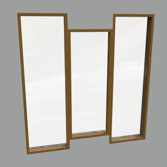
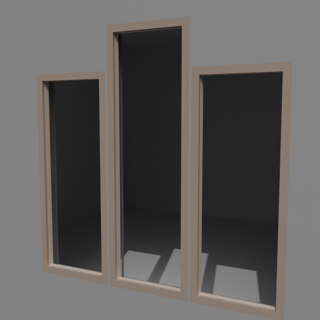
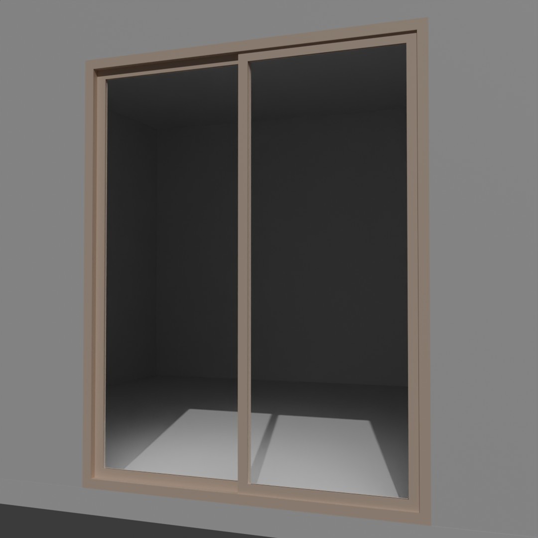
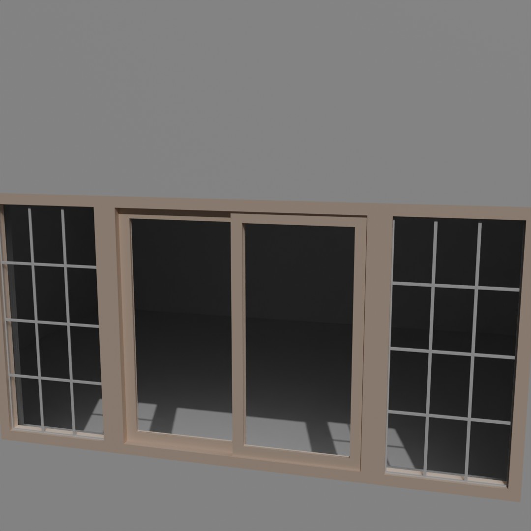
Overview
What is it?
The basic window generator is a design process tool designed for Architectural projects in Blender. Built on Geometry Nodes, the tool works through a modifier and creates procedural window meshes and their corresponding plan-view symbols. It is intended to enable quick and easy design iteration and to provide a preview of how a window configuration will look in a space.
How Does it Work?
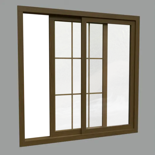
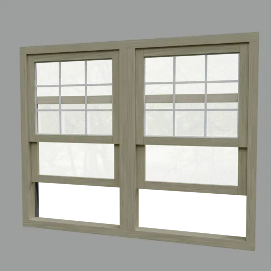
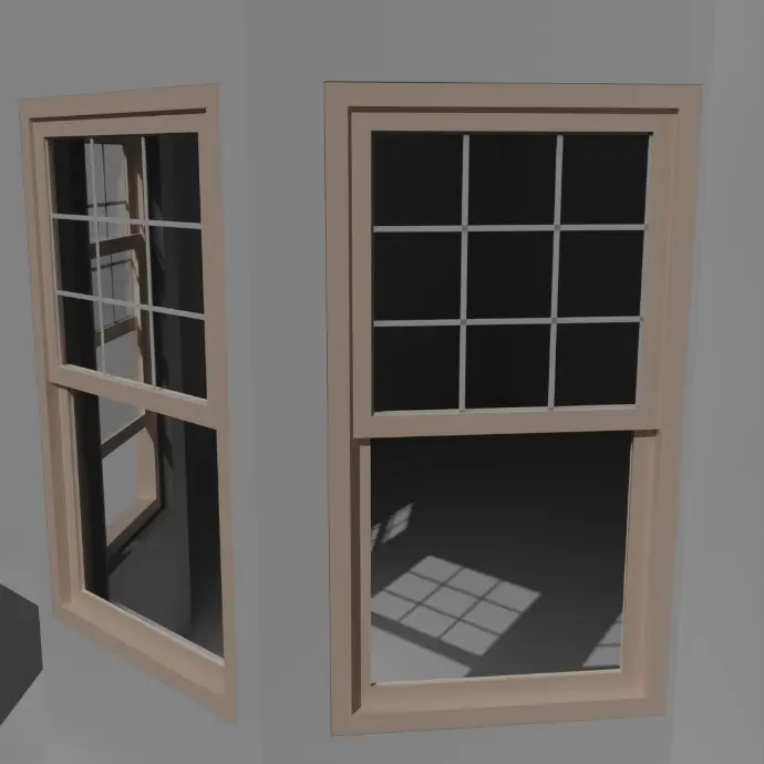
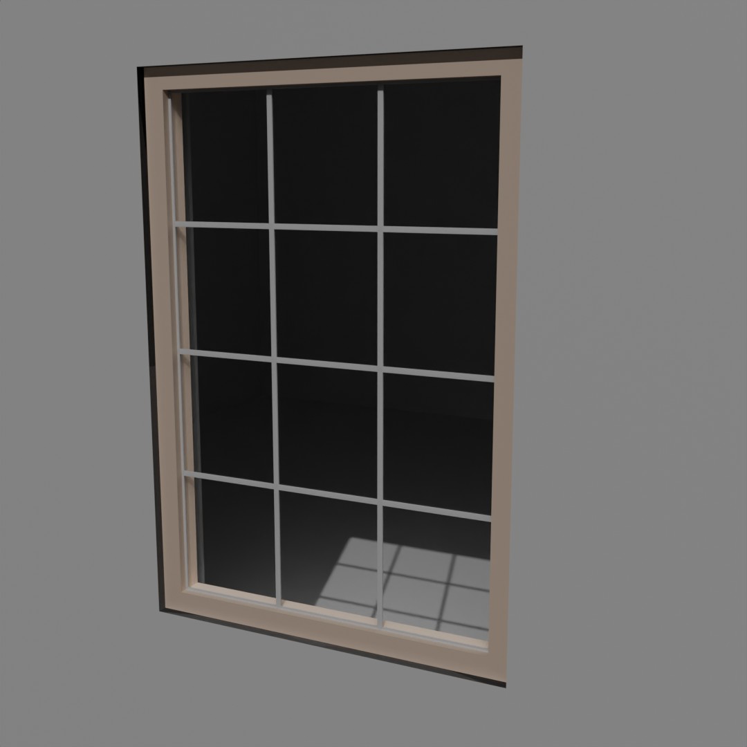
The window generator tool works by generating a fully procedural window mesh based on the user-input dimensions and settings. These settings are found and used as a modifier, and users can switch between rectangular picture, sash, and sliding windows in any size, with or without basic grilles. Window meshes and symbols can be switched between using the menu in the modifier on an individual basis or across the project using the manual override in the node system.
Note: As of Release 1.1, generated meshes now have procedural UVs!
Where Can I Find it?
Note - the BlenderKit version is a standalone and the ArtStation version ships with my other free tools.
This tool is dependent on features introduced in Blender's 4.1 release and will not function in earlier versions.
Released: July 30, 2024
Supported Blender versions: 4.1 - 4.2
Release Notes:
- Added descriptive tooltips to the inputs in the modifier. These are visible when the mouse hovers over each input.
- Added UV unwrapping.
- Two new procedural materials: Wood and Painted Wood.
- Updated Materials panel to sync with the new Basic Door Generator.
- Adds a material selection menu and inputs to control the color and roughness of the provided materials for the Frame and Grilles - all directly from the modifier.
Released: June 6, 2024
Supported Blender versions: 4.1 only
License
This tool can be used for personal or commercial projects without royalties. Attribution is deeply appreciated but not required.
The user may not
distribute copies of the tool without the express, written permission of the Developer.
Warranty Disclaimer: All work produced by this Developer is provided "AS IS". The Developer makes no other warranties, either express or implied, and hereby disclaims any implied warranties, including any warranty of merchantability and warranty of fitness for a particular purpose. The Developer
makes no representation or warranty of any kind, express or implied,
regarding the accuracy, adequacy, validity, reliability, availability,
or completeness of any information.
How to Navigate this Guide?
The table of contents on the left side of the page lists the major sections of the guide. The Getting Started section at the top goes over the basic preparatory steps to prepare for use of the tool, and the Basic Settings section goes over the options visible at the top of the modifier. The remaining sections go over the different panels in the modifier, with the same names and in the same order as they appear in the modifier.
Feature version 1.1 and above
Getting Started
Importing the Tool
There are a few ways to get the tool into a project file. If the user is downloading the tool from BlenderKit, it's as simple as dragging and dropping the file into a new or existing project. It the user is downloading the tool from Artstation, there are a few different ways to get the tool into a file. The user can start the project in a copy of the download file or the node tree can be appended or linked into an existing file.
The first method works if the user is just
starting a new project - The user can just use the download file the
tool ships with (or make a copy of it) as the base file for the project.
The other methods are Appending and Linking. Appending copies the tool and all its references into the new file and Linking basically uses the original file as a reference. Appending is best if the user is going to be moving files around because it isn't dependent on the download file staying in the same location. Linking requires both files to stay put, but doesn't clutter up the scene collection with all the components. To do either of these methods, simply open a Blender project, go to the File menu, and click Append or Link. From here, navigate to where the tool was downloaded and double click the folder labelled "Free Archvis Tools 1.0", which should have the Blender logo on it. Scroll down to find the folder labelled "Node Tree" and double click into this as well. Near the top of this folder there is a file called "Basic Window Generator". Left click this file to highlight it, then click Link or Append to add it to the file. The tool will have to be manually added to a mesh.
Note: It is possible to import the actual mesh that the modifier is applied to in the sample file - but this only works with the Append method. If the Linking method is used this will result in the modifier being greyed out and unusable.
The Input Mesh
This window generator functions by instancing generated window meshes on each vertex in the mesh the modifier is added to. To use the tool place a single vertex at floor level on the outside of the wall; centered on where each window should be, then add a geometry nodes modifier and select the "Window Tool". These vertexes can be moved around in edit or object mode to adjust the location of the window in real time.
To control each window independently: keep each vertex as a separate object.
To control multiple window instances together: join the vertexes into a single object to sync their dimensions and settings.
Setting up the Boolean
In order to punch the hole for the window, users will need to set up a basic boolean modifier. This modifier must be placed on the wall object, or the object that is going to have the hole punched through it.
The set-up for this is pretty simple. Select the wall that the window is going in, go the to modifiers tab (wrench icon), and add a boolean modifier. Make sure that "Difference" is selected at the top of the modifier, and that the Solver is set to "Exact" for better results. I've found that the "Fast" solver generates some odd results.
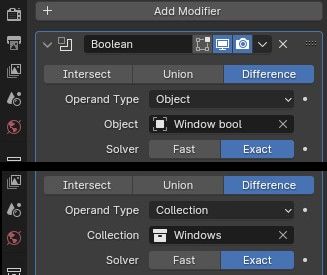
If there's only going to be one window, just add the mesh which is hosting the window to the object input and the hole should be cut around the window automatically. If there's going to be multiple windows punched into one wall, it may be easier to place all the window objects into their own collection, and change the boolean modifier's operand type to "Collection".
Don't apply the boolean until the window size and position have been finalized. This will lock the size and position of the hole in the wall mesh.
Basic Settings
The general settings at the top of the modifier, these are always visible where the other settings are nestled into closable tabs.
Window Type
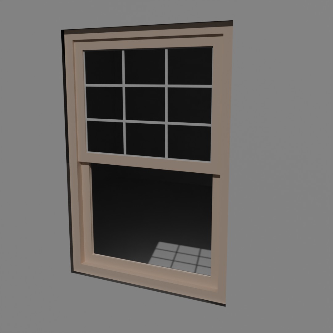
Situated at the very top of the modifier, the Window Type menu is where the different window types can be selected between. In the basic version, this includes picture windows, sash (vertical sliding) windows, and sliding (horizontal sliding) windows.
Window Rotation
The geometry node automatically orients all windows with the outside facing in the negative Y-direction, and does not recognize the orientation of the wall it intersects. If the window is out of alignment with the wall, the Window Rotation input can be adjusted to align the window to match the wall.
NOTE: this only supports rotations in the Z-direction
Custom Mesh
The Custom Mesh toggle is for replacing the procedural window with a user-supplied mesh. Once the dimensions of the window generator are matched to the window waiting for import, simply check this box to remove all window elements except for the boolean box. This will leave a boolean hole appropriately sized and placed, which the user-supplied mesh can then be moved into. There is currently no function to do this automatically.
Dimensions
The dimensions tab in the modifier is pretty much what it sounds like. The numbers input here afford the user total control of the size and appearance of the window. As the actual dimensions of window components are calculated from the input dimensions, this tool should work with any units.
Window Width
This is the width (side-to-side) of the window. It includes the frame.
Window Height
This is the height of the window, from sill to top. Like width, it includes the frame.
Window Depth
This is the depth (inside to outside) of the window unit. It can be, but isn't necessarily, the same as the wall thickness.
Sill Height
The height of the window sill measured from the floor.
Frame Thickness
The thickness (side-to-side) of all frame elements, including panels and the overall frame.
Window Inset
How far back the window is inset from the outside edge of the wall.
Glass Thickness
The thickness of the pane(s) of glass which are inserted in the windows.
Wall Thickness
The thickness of the wall that the window is being inserted in. This controls the depth of the boolean hole punch. If the wall thickness is unknown, overestimate it to ensure that the hole is punched all the way through.
Materials
The generated meshes can have up to three different materials which are applied through the Geometry Nodes, and can be customized in this tab. The materials are for the frame, glass, and grilles. Meshes are procedurally unwrapped, and the grain direction of the provided wood materials is determined by the longest edge in each component.
Note: Adding materials in Blender's material properties will not affect the meshes.
Frame/Grille Material
These drop-down menus allow the user to choose which preset material to apply to the named part of the window, or if a custom material will be imported. The included materials are Wood, Painted Wood, and Vinyl, which are all procedurally generated.
Frame/Grille Color
These color inputs allow the user to choose any color to apply to the preset material selected above. Note that these colors don't affect imported custom materials.
Frame/Grille Roughness
The roughness sliders adjust the roughness of the preset materials. Note that, like the colors, they don't affect imported custom materials.
Frame/Grille/Glass Custom
If Custom is selected in the Material menu above, these inputs are where a custom material is imported. The Glass material currently only supports custom.
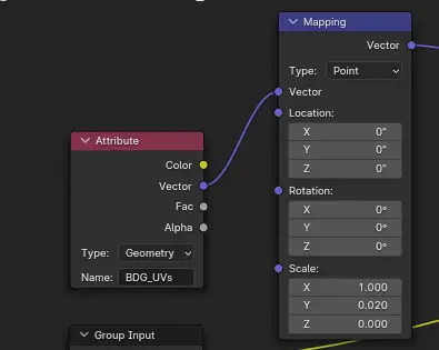
Note: When importing custom materials, use the "BDG_UVs" attribute for the vector instead of the generic UV texture coordinate. This attribute is where the procedural UVs are stored, and is the only way I know of to access them.
Grilles
Optional window grilles. These are set inside the glass, and the basic version only offers evenly spaced grille designs.
Grille Visibility
This drop-down menu allows the user to select which window pane(s) grilles are visible on.
Grille Thickness
The grille thickness input controls the thickness of the individual grilles in the windows.
# Horizontal
This is an integer input which allows the user to control how many horizontal grilles they want in their window. The input is capped at 15.
# Vertical
This is an integer input which allows the user to control how many vertical grilles they want in their window. The input is capped at 15.
Plan View Settings
Each window type has a corresponding plan-view symbol which scales to match the window. This section controls those symbols and their visibility for when the user wants to render a plan versus a perspective view.
Visibility
This drop-down menu allows the user to toggle between viewing the window mesh or it's corresponding plan-view symbol. It is controlled for each object individually.
Symbol Line Thickness
This input sets the diameter of the lines which make up the window symbol.
Manual Override
Having to change every single window object from mesh to symbol and back is frustrating, especially that one moment when a window or two was missed or toggled by accident, so this tool incorporates a master switch function to temporarily override all individual visibility settings. This works both ways - it can force everything to plan view or to mesh.
There is one caveat though - as modifier settings only affect the object they're applied to, the master switch has to be accessed from the node system. It is not hard to use, though. In the geometry nodes tab, at the very top of the node tree, there is a mid-grey box labelled "PLAN VIEW MANUAL OVERRIDE" with a single node group inside. Left click this node group and click tab to go inside of it.
There are five nodes inside the tree, but the user only needs to worry about two of them. The second node from the right is a switch node labelled "True to Override", just click the checkbox next to where it says "Switch" to activate the override function. The box should turn blue with a check mark.
From here, go down and left to the menu switch node labelled "OVERRIDE" and use the second drop-down from the top to choose between mesh and plan symbol visibility. As long as the switch is active, the setting in this node will be used for all windows in the scene. To deactivate the override, just click the checkbox next to where it says "Switch" again so that it shows an empty grey box. This will default the node system back to the individual settings saved in the modifier.
Animation
The window generator has a very basic animation function, just for fun. It has no effect on picture windows, as these are fixed, and only affects the inside pane of operable window types. The input allows the user to input a value, in the scene's units, for how far the window should open. Any value whatsoever can be put in this field, but the node system will clamp it to values calculated from the user-input dimensions. This ensures that the window pane will stay inside of its frame, regardless of the dimensions of the window.
Example Gallery
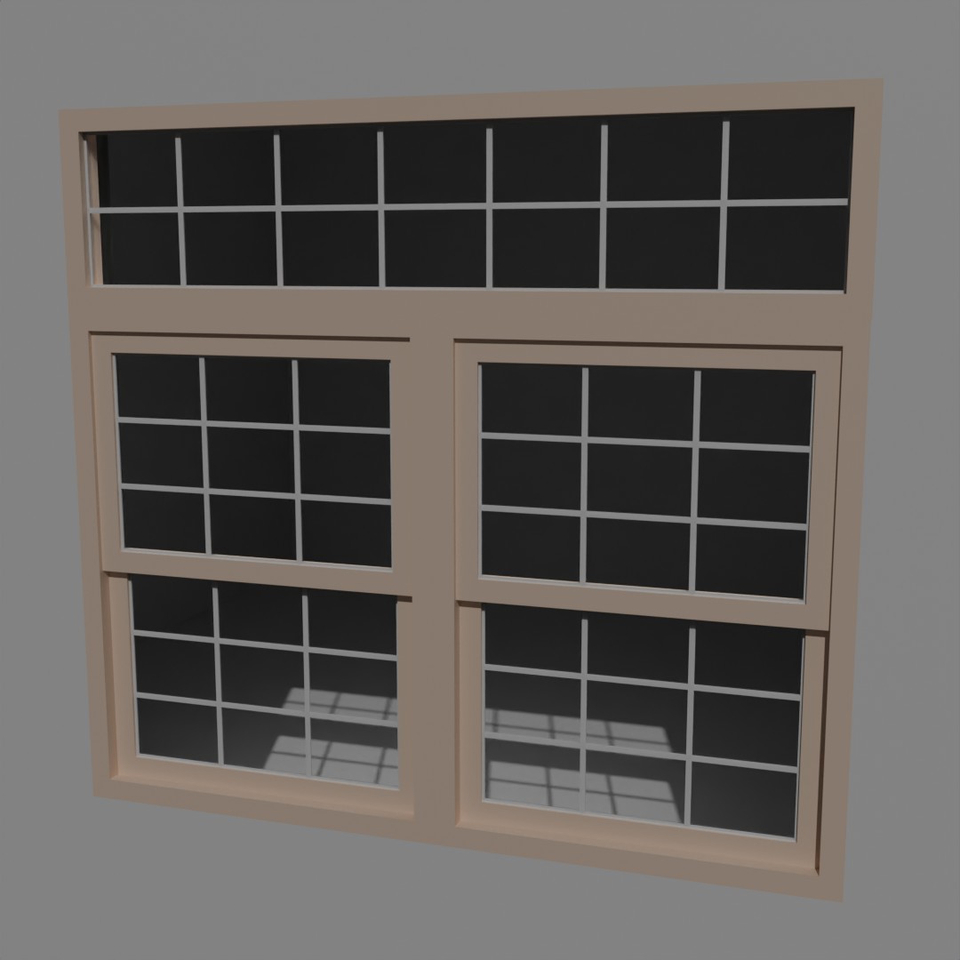
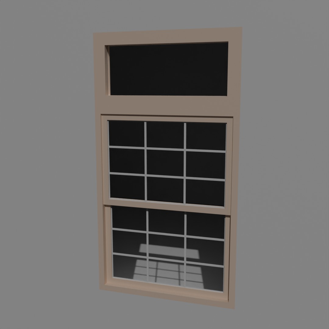
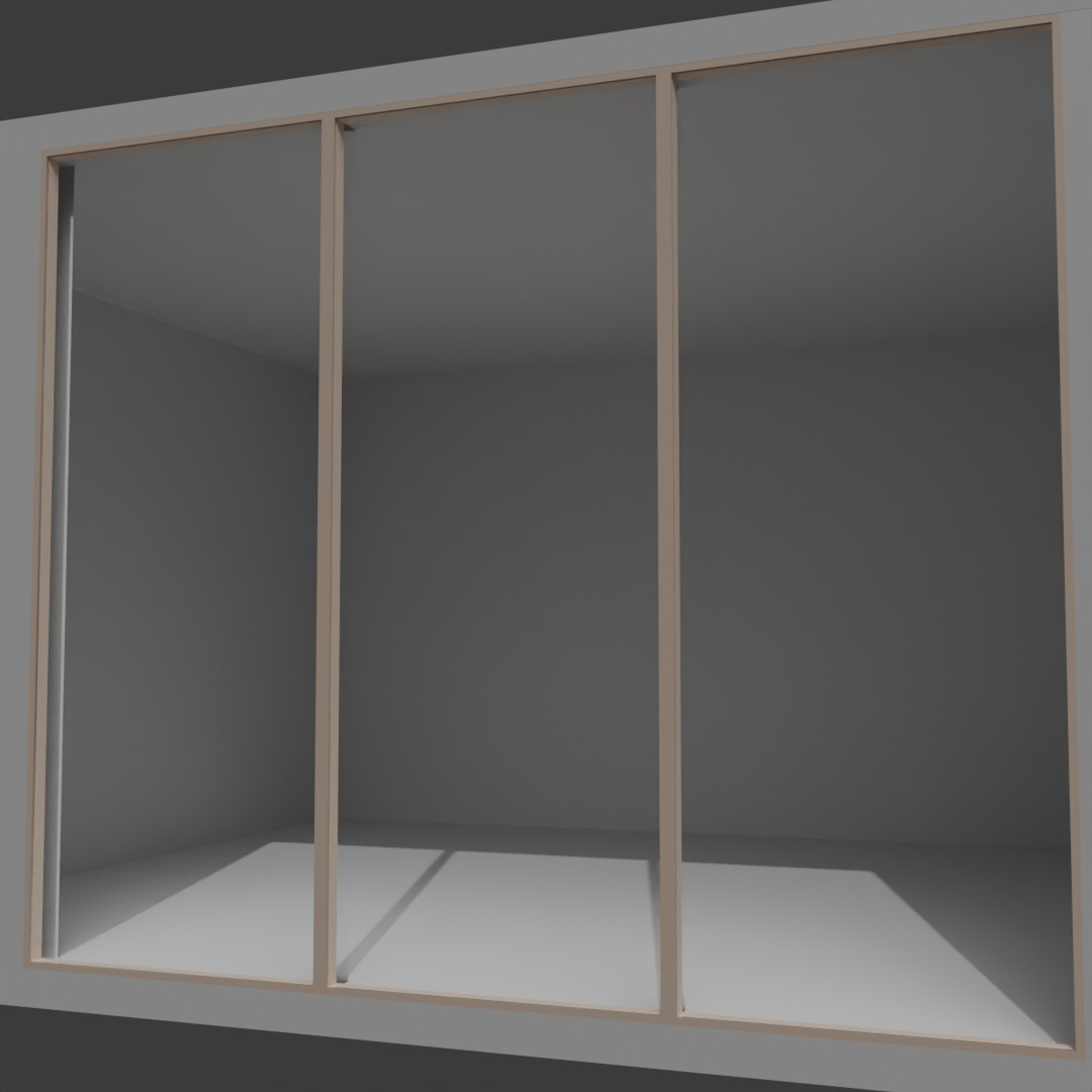
The images below are examples of some of the results that can be achieved with this generator. All of these are placed in a basic scene with a room and either a single sun object or an HDRI to provide the light. The walls are just Blender's default material. Some window setups use a single window object, others use multiple window objects placed together to achieve an effect. None of them took more than a few minutes to set up and render.
