Overview
What is it?
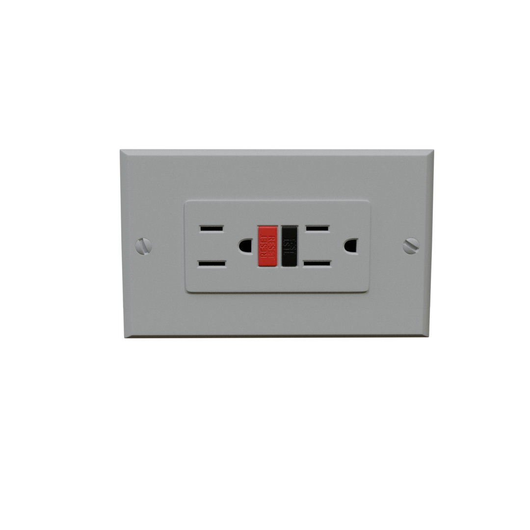
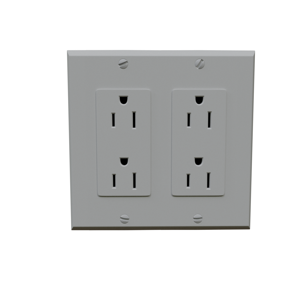
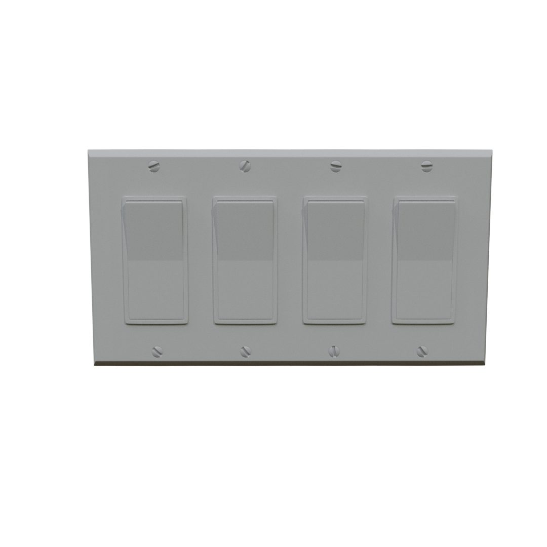
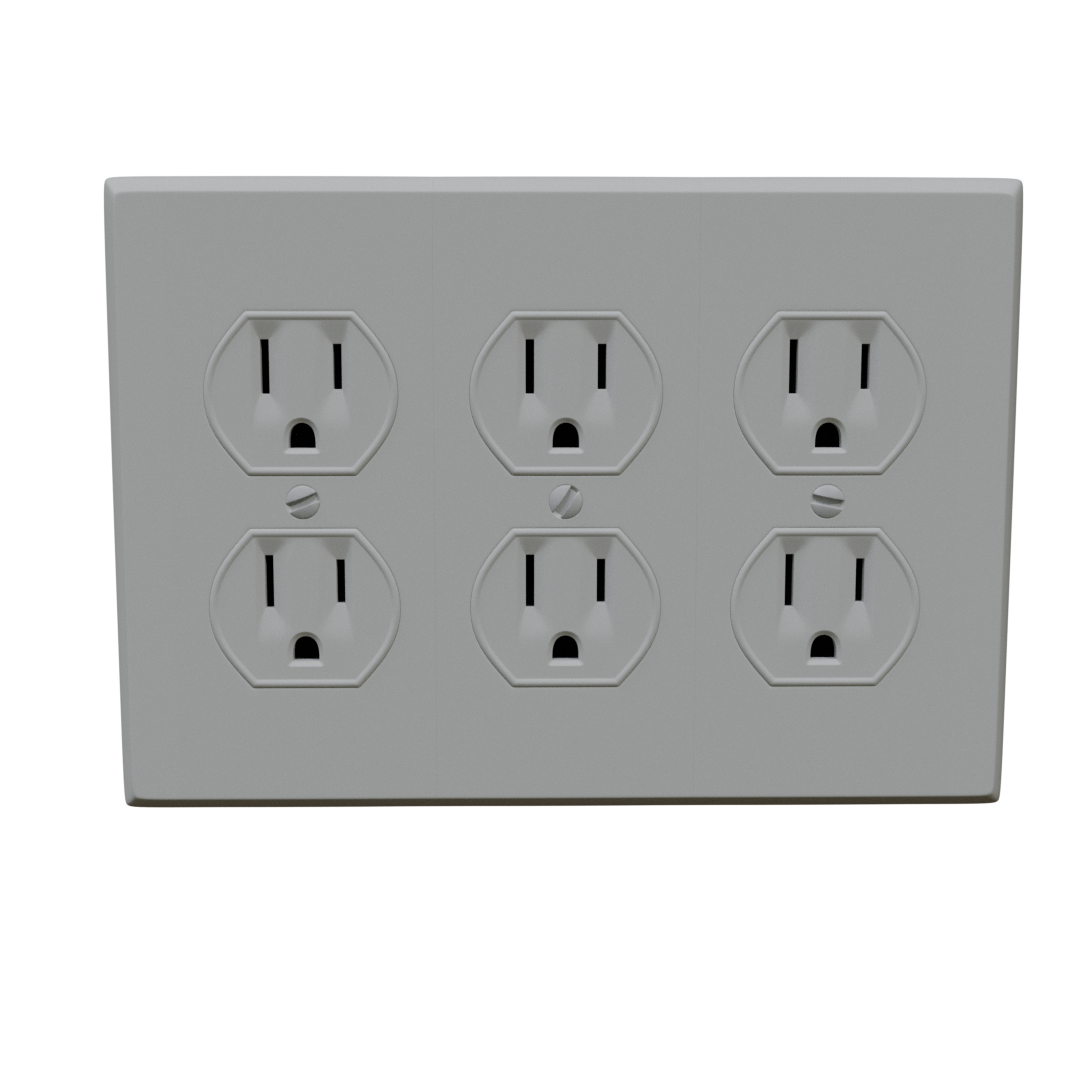
The Basic Outlet and Switch Tool is a free geometry-nodes based tool for Blender. It works through a modifier to enable easy generation and placement of electrical outlets and switches. The tool includes render-quality models with baked PBR texture sets for three basic types of outlets and one basic type of switch.
How does it work?
The tool works by instancing modular components to create a unit with up to 10 outlets or switches of the selected type, complete with screws and wallplate. The position and orientation of this unit and some of its components can be controlled by the user with the settings in the modifier.
Where can I find it?
Note - the BlenderKit version is a standalone and the ArtStation version ships with my other free tools.
This tool is dependent on features introduced in Blender's 4.1 release and will not function in earlier versions.
Released: June 6, 2024
Supported Blender versions: 4.1 only
License
This tool can be used for personal or commercial projects without royalties. Attribution is deeply appreciated but not required.
The user may not
distribute copies of the tool without the express, written permission of the Developer.
Warranty Disclaimer: All work produced by this Developer is provided "AS IS". The Developer makes no other warranties, either express or implied, and hereby disclaims any implied warranties, including any warranty of merchantability and warranty of fitness for a particular purpose. The Developer makes no representation or warranty of any kind, express or implied, regarding the accuracy, adequacy, validity, reliability, availability, or completeness of any information.
How to Navigate this Guide
The table of contents on the left side of the page lists the major sections of the guide. The Getting Started section at the top goes over the basic preparatory steps to prepare for use of the tool, and the Basic Settings section goes over the options visible at the top of the modifier. The remaining sections go over the different panels in the modifier, with the same names and in the same order as they appear in the modifier.
Note: Throughout the documentation and in the tool itself, the outlet and switch components are referred to as "accessories" and the complete mesh (including the accessories, wallplate, and screws) is referred to as the "unit".
Getting Started
This tool functions by instancing a unit on each vertex in the mesh the modifier is added to, and there are two different techniques for placing the units. Manual application is more stable, but Snap as Wall Object is more versatile.
Importing the Tool
There are a few ways to get the tool
into a project file. If the user is downloading the tool from
BlenderKit, it's as simple as dragging and dropping the file into a new
or existing project. It the user is downloading the tool from
Artstation, there are a few different ways to get the tool into a file.
The user can start the project in a copy of the
download file or the node tree can be appended or linked into an
existing file.
The first method works if the user is just starting a new project - The user can just use the download file the tool ships with (or a copy of it) as the base file for the project.
The other methods are Appending and Linking. Appending copies the tool
and all its references into the new file and Linking basically uses the
original file as a reference. Appending is best if the user is going to
be moving files around because it isn't dependent on the download file
staying in the same location. Linking requires both files to stay put,
but doesn't clutter up the scene collection with all the components. To
do either of these methods, simply open a Blender project, go to the
File menu, and click Append or Link. From here, navigate to where the
tool was downloaded and double click the folder labelled "Free Archvis
Tools 1.0", which should have the Blender logo on it. Scroll down
to find the folder labelled "Node Tree" and double click into this as
well. Near the top of this folder there is a file called "Basic Outlet & Switch Tool". Left click this file to highlight it, then click Link
or Append to add it to the file. The tool will have to be manually added
to a mesh.
Note: It is possible to import the actual mesh that the modifier is applied to in the sample file - but this only works with the Append method. If the Linking method is used this will result in the modifier being greyed out and unusable. There are two sample meshes in the file, one for each application method offered in the tool. If both methods are desired in a file either append both meshes at once (only clicking "Append" once) or use the instructions below to convert between the two methods after appending either. DO NOT RUN A SECOND APPEND TO GET THE OTHER METHOD INTO A FILE - this creates a second copy of the tool, its materials, and all of the kit parts it uses, which will double the file space that the tool will take up in the project.
Note: When using append, I've found it's best to have an empty collection ready and selected before appending the files. This way all the components that the tool uses will import into their own collection which can be turned off and moved around easily. I recommend using the little checkbox on the collection folder to exclude the components from the view layer, as this prevents the mass of loose pieces from showing up in renders and does not impact the visibility of meshes generated with the tool.
Applying the Tool to a Mesh
The process of actually applying the tool is pretty straightforward. If the user is starting a project in a copy of the provided file or appending a sample mesh (see above), units can simply be copy-pasted or dragged and dropped into the scene. Any copy which has its own object in the Outliner can be modified individually.
If the user is importing just the tool into an existing file or needs to apply the modifier to a pre-made mesh, the tool can be manually applied. To do this, navigate to the Modifiers tab in the properties panel and click the Add Modifier button. From here click the Geometry Nodes option which should be directly under the search bar at the top of the menu. This adds a modifier block to the mesh, with a large button labelled "New" to the right of a small drop-down menu. Click on the drop-down menu and select the option labelled "Outlet and Switch Tool 1.0". The default outlet should appear over each vertex in the mesh.
Manual Application
This method allows precision placement of the units. To start, place a
single vertex at floor level at the base of the desired wall;
centered on where each unit should be, then add a geometry nodes
modifier and select the "Basic Outlet & Switch Tool". These vertexes can be moved
around in edit or object mode to adjust the location of the unit(s) in
real time. When applying the modifier in this way, the Snap as Wall Object checkbox is disabled by default. This is the easiest method to use if precision is required or preferred.
To control each unit independently: keep each vertex as a separate object.
To control multiple units together: join the vertexes into a single object to sync their settings.
Snap as Wall Object
Note that this mode is temperamental - it runs afoul of a bug in
Blender itself which causes objects snapped in this way to come in at
odd rotations sometimes. This bug has been reported to the Blender team and will hopefully be investigated soon.
This allows users to just snap their units to the wall instead of or in addition to using the position settings. What this means is if the asset is dragged and dropped from the outliner or the asset browser it will snap with the back flush against any surface, but it can take a little extra work to get it working correctly and it works best with vertical surfaces.
When
downloading the tool from BlenderKit this is enabled automatically as
requested by the site moderators. When adding the modifier to a user created mesh, it is disabled automatically. The ArtStation version has two meshes with the modifier applied - the mesh on the left has snapping enabled and the mesh on the right does not.
To disable Snap as Wall Object: When the unit is snapped to a surface, Blender rotates it to ensure it is oriented correctly. It will look like the rotation has been messed up when the toggle is turned off, but simply applying the rotation will snap the unit back into the default position. From here, simply snap the vertex the unit is instanced on to the base of the wall.
To snap multiple units: Do Not download multiple copies from BlenderKit into a single project, this will add multiple copies of all the files and cause visibility issues. Instead, download it once and either duplicate it in the viewport, drag and drop copies from the outliner, or add the original mesh with snapping enabled to the asset browser, and drag and drop additional copies from there.
To enable Snap as Wall Object manually: Create a unit using the manual method, and set the Unit Height to zero before enabling snapping. Once this is done, left click on the mesh in the outliner and drag a copy into the scene to snap. The user can also use the asset browser for this, which may be easier to keep track of in larger projects.
To use precision with snapping enabled: There are a couple considerations here. Firstly, the user can disable Snap as Wall Object as described above, or leave it on. If leaving it on for units snapped to walls facing in the +Y direction, the user will need to set the Y-rotation in the object transforms to 180 degrees. For units facing the -Y direction, the Y-rotation needs to be set to 0 degrees. Basically adjust this value so that, when a value is entered in the Unit Height input the vertex is underneath the unit. If turning it off, follow the steps above for disabling Snap as Wall Object and use the Unit Rotation input in the modifier to align the unit with your wall. Once the unit is aligned, go into edit mode and snap the vertex that the unit is instanced on to the base of the wall, and set the desired height in the modifier.
If the unit snaps in a weird orientation: This is caused by the bug mentioned above - the user can either rotate it in object mode or play with the Is Sideways and Flip Accessory toggles to correct it.
Basic Settings
The general settings at the top of the modifier, these are always
visible where the other settings are nestled into closable tabs.
Accessory Type
Situated at the very top of the modifier, the Accessory Type menu allows the user to select between the available types of accessories. In the basic version, this includes 15-amp outlets in the traditional and decorator styles, a 15-amp decorator style GFCI outlet, and a simple rocker switch.
Flip Accessory
The flip accessory checkbox does exactly what it sounds like - rotating each accessory in the unit by 180 degrees. This can be used to add upside-down outlets or to toggle the switch.
# Accessories
This is an integer input allowing the user to determine how many accessories should be in the unit, with the tool supporting a maximum of 10. Negative numbers or zero will read as an input of 1, and numbers in excess of 10 will be read as 10. The basic version does not support combination plates, so all accessories in a single unit will be the same.
Unit Position
Unit Height
The height of the unit above the floor. This is measured in scene units.
Floor to
By default, the unit height is measured to the center of the unit. The Floor to menu allows the user to change this to measure height to the top or bottom of the unit.
Unit Rotation
This setting rotates the unit in the Z-direction. As the tool itself can't read the orientation of the wall, this setting can be used to align the unit to the wall if it isn't already.
Is Sideways
This toggle turns the unit sideways on the wall.
Randomization
Randomize Screws
This toggle is activated by default, and adds a random orientation to each screw in the unit. Unchecking it sets all screws to be oriented in the same direction.
Random Seed
This seed is for the random number generator that rotates the screws.
Examples
The image below has some examples of what can be achieved with this tool. This full set of examples took only a couple of minutes to set up and render, and demonstrates each of the accessory types available with this tool.


